Cosimulation
This document provides an overview of the internal workflow of the cosimulation used in Dynamatic. Cosimulation is utilized to verify the correctness of a circuit and consists of two parts. Firstly, the execution of the kernel’s source code and, secondly, the simulation of the kernel’s RTL implementation generated by Dynamatic. The circuit is assumed to be correct if the outputs of both steps match. We will focus on the second step in this document.
note
Information about using verification and cosimulation can be found here.
Sections and overview:
- Testbench generation: This section explains the steps to create the testbench in
tools/hls-verifier/hls-verifier.cpp - Simulator Options: This sections lists the supported simulators.
Testbench generation
note
Depending on the --hdl flag for Dynamatic’s write-hdl command, the testbench is either generated in VHDL or Verilog.
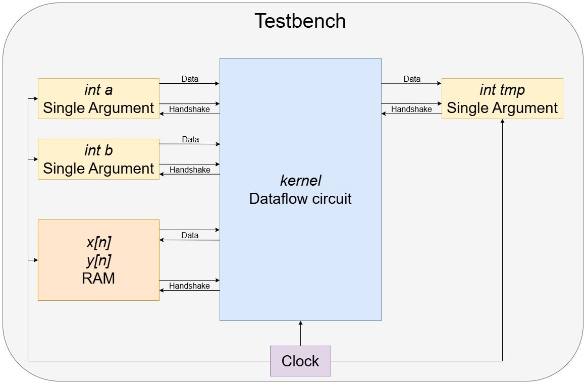
In Dynamatic’s compilation step, the source code is translated into an equivalent dataflow circuit. To simulate the HDL implementation of this dataflow circuit, additional helper circuitry is required, known as the testbench. In addition to a clock signal and signals to start and finish the simulation, the testbench provides the input arguments to the kernel and collects the outputs.
We will discuss how the testbench is generated next by means of a simple kernel. A simplified representation of the testbench is given in the figure below.
int kernel(int y[N], int x[N], int a, int b) {
    int tmp = y[0];
    for (unsigned i = 1; i < N; i++) {
        tmp = a * tmp + b * x[i];
        y[i] = tmp;
    }
    return tmp;
}
Auxiliary Processes
The first step of the testbench generation is to create a VHDL file called tb_<kernel_name>.vhd resp. a Verilog file tb_<kernel_name>.v which will contain all processes and instances needed to simulate the kernel. It is the top-level module for simulation.
Standard HDL boilerplate and processes for generating a clock signal, a reset signal and signals for starting and ending a simulation are written in Verilog or VHDL in tools/hls-verifier/include/HlsTb.h and are copied to the testbench file.
Constants
Constant values such as the clock period or reset latency can be defined with the function declareConstant(). The appropriate HDL implementation is then written to the testbench file.
Signals
Declaring signals that hold a value and are updated in procedural blocks need to be declared differently from signals that only connect two modules.
Therefore, there are two functions to declare signals: declareReg() and declareWire().
Verilog throws an error if the wrong type is selected. VHDL, on the other hand, does not make a distinction between the two types and both functions emit the same VHDL code.
Connections between two modules are declared using the function declareWire().
Single Argument
Single value input arguments (e.g. int a and int b) and output values (e.g. int tmp) are handled by the single argument module.
This module communicates by handshake signals with the dataflow circuit.
For every single valued input/output, a single argument module is instantiated from the template in tools/hls-verifier/resources/.
RAM
To load and store values from arrays (e.g. int x[n] and int y[n]), the testbench has a RAM module.
It is connected by data and handshake signals to the dataflow circuit.
The template is located in the same directory as the single argument.
Global Completion Signal
The simulation is finished when all output modules received their value. To collect all valid signals from the output instances the join_tb module is used.
Same as for the single argument and the RAM, the template is located in tools/hls-verifier/resources/.
Writing Output File
When the simulation is finished, the contents of the RAM and single argument modules are copied to the output file.
The HDL implementation for this process is given in hlsTb.h.
This concludes the testbench generation, and the circuit is now ready to be simulated.
Simulator Options
There are four different simulators currently supported by Dynamatic. ModelSim, Vivado Vitis, GHDL and Verilator. The first two can simulate both Verilog and VHDL files, where GHDL only works with VHDL and Verilator only with Verilog files.
warning
To use GHDL or Verilator, the correct HDL must be specified during Dynamatic’s write-hdl command.
Dynamatic’s simulate
The simulator can be selected with the flag --simulator during Dynamatic’s simulate command.
- ModelSim:
--simulator vsim - Vitis Vivado:
--simulator xsim - GHDL:
--simulator ghdl - Verilator:
--simulator verilator
Every simulator compiles all files in the /HDL_SRC directory and then starts the simulation with the testbench as top level module.
The implementation of the simulators is in tools/hls-verifier/include/Simulators.h. We will now briefly discuss every simulator.
ModelSim
When using ModelSim, Dynamatic creates a .do file with all necessary commands to elaborate, compile and execute the ModelSim simulation.
Dynamatic then passes this .do file when calling ModelSim.
Vivado Vitis
Dynamatic calls the xelab function of Vitis with the -R flag.
This elaborates and compiles the testbench and simulates the design.
GHDL
GHDL is executed using a shell script. All HDL source files are imported into GHDL, compiled and simulated.
Verilator
The Verilator main function is copied from tools/hls-verifier/resources/verilator_main.cpp to the working directory.
A shell script is used to call Verilator and run the simulation.